G.726 Voice Transcoding Subsystem

The Voice Transcoding Subsystem (VTS) is a software product, typically used in circuit-switched trunking applications, which implements T1 and E1 transcoding as specified in the ANSI T1.302a- 1992 and ITU-T G.761 specifications. VTS compresses two T1 or E1 lines into a single line or decompresses a single span into two. Compression is accomplished using G.726. Although it can be adapted to other processors, VTS is specifically optimized for the Texas Instruments TMS320C6000 DSP. In full-duplex mode it operates on a pair of TI TMS320C6211-150 processors, or on a single more-powerful member of the ‘C6000 product family.

VTS replaces the transcoder chipset from Brooktree (now Mindspeed, a subsidiary of Conexant) that includes the Bt8110 ADPCM Processor and the Bt8200 ADPCM Formatter. VTS emulates the control structure of those chips to maintain compatibility with legacy control software.

VTS consists of four modules: E1 Compressor, E1 Decompressor, T1 Compressor, and T1 Decompressor. The VTS product deliverable includes example DMA code for controlling software transfers on a ‘C6211 processor, but generally the OEM must implement code for interfacing with the hardware.

Example hardware-configuration software is also supplied for the Multi-Channel Buffered Serial Ports and the DMA channels that are standard on the ‘C6000 line. The OEM can replace or modify this code as required.

Features

  • Based on Commetrex’ industry-leading G.726 implementation
  • Source- or object-code licenses
  • Comprehensive documentation
  • Standards based

Benefits

  • Low recurring cost due to low component count
  • Low implementation cost
  • Fast time-to-market

Technical Overview

The VTS product consists of three major functions:

  • Compressing/Decompressing Signaling
  • Compressing/Decompressing Timeslots
  • Timeslot Interchange

VTS handles signaling in-band via robbed-bit signaling or out-of-band via dedicated memory buffer. A micro-controller updates out-of-band signaling via the Host Port Interface (HPI) or via OEM-supplied hardware and software that extracts signaling in some other fashion. At the decompressor, signaling is output either in- band, via robbed-bit signaling, or out-of-band, via a memory buffer.

Control Processor

For T1, ANSI T1.302s specifies three formats for signaling: Bundled Mode, Transition Mode, and Robbed-Bit Mode. VTS implements Bundled Mode and Robbed Bit Mode¹.

For E1, VTS supports the line format and pass- through 60-channel format given in ITU recommendation G.761. Signaling according to G.761 is not supported in VTS but can be provided from the external control processor.

For timeslot compression, VTS utilizes G.726 at 32-kbps or 24-kbps, or transparent encoding at 32-kbps or 64-kbps. Transparent encoding permits modem channels to be passed without compression. The encoding and decoding of each timeslot is individually configurable.

For G.726 compression, VTS utilizes the unique architecture of the ‘C6000 processor by operating the processor in an SIMD fashion. The ‘C6000 processor has two distinct data paths, A and B. Each data path has the same complement of four functional execution units. The processor is capable of executing a single instruction on each of these eight functional units on each bus pass. VTS utilizes the parallel data paths to allow two simultaneous samples to be processed through the G.726 algorithm in parallel.

Both ANSI T1.302 and G.761 specify permissible timeslot rearrangements. VTS implements these rearrangements while meeting the minimum delay requirements of each specification.

Packaging

The VTS is packaged as three components: the G.726 module, transcoding modules, and the hardware interface. G.726 processing is controlled directly by the transcoding modules. The transcoding is controlled via a set of memory-mapped registers. These registers can be accessed via the Host Interface Port (HIP) available on the C6x DSPs. The transcoding operation is performed exclusively between memory buffers. Thus, the G.726 and transcoding functions do not interface to the hardware environment.

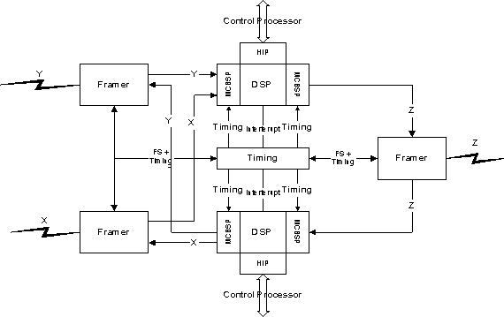
Example code is supplied for configuration of chip peripherals for a dual TMS320C6211 configuration, shown below. The example code is built on the TI-supplied Chip Support Library. This provides portability to other C6x family members.

G.726

Brooktree Compatibility

The Voice Transcoding Subsystem (VTS) was designed to replace two Brooktree functional chips, the Bt8110 ADPCM Processor and the Bt8200 ADPCM Formatter with one or two open-architecture catalog DSPs from the TI TMS320C6000 family. The VTS maintains the control interface of these chips.

Example Configurations

The diagram above shows a typical implementation of the VTS. In this example, two T1/E1 framers are cascaded to interface the X and Y channels to one of the McBSP on the DSP. Another framer is used to interface the Z channel to the other McBSP. A micro- controller is used to configure the VTS. In out- of-band signaling mode, the micro-controller is responsible for transferring signaling between the framers and the DSP.

The configuration above also utilizes two DSPs, the upper for encoding, and the lower for decoding. Separate McBSP ports are used to interface to the framers. For the upper DSP, the receive channels of both McBSPs are used to interface to the incoming T1 (X, Y)/E1 (A, B) channels while only a single transmit channel is used to interface to the compressed T1 (Z) or E1 (C) channel. The reverse is true for the lower DSP.

Resource Requirements

The VTS resource requirements are given in the table below.

Function MCPS² Code(Kbytes) Data(Kbytes)
Encoder 131 30 6.4
Decoder 145 38 6.4


Data space includes frame and signaling buffers and control registers, as well as G.726 context areas.

The algorithms also require a superframe indicator for processing robbed-bit signaling.

¹Transition Signaling Mode is not currently supported. ²C6211 cache constraints result in higher MIPS than on other members of the C6x family.

References

1. ANSI T1.302a-1992 Digital Processing of Voice-Band Signals – Line Format for 32-kbit/s ADPCM (channel-control templates and robbed-bit signaling alarm transmission)

2. ANSI T1.303-1989 Digital Processing of Voice-Band Signals – Line Format for 24-, 32-, and 40- kbit/s ADPCM

3. ANSI T1.310-1991

4. ITU-T G.726 (1990) General Aspects of Digital Transmission Systems: Terminal Equipment. 40-, 32-, 24-, 16-kbit/s Adaptive Differential Pulse Code Modulation (ADPCM)

5. ITU-T G.727

6. ITU-T G.761 General Characteristics of a 60-Channel Transcoder Equipment (E1 ADPCM compression)